The FARO ScanArm, coupled with FARO CAM2 2019 software, offers a powerful solution for 3D measurement and inspection. This portable coordinate measuring machine (CMM) allows users to accurately capture dimensional data directly from physical parts and compare it to CAD models. Whether you're reverse engineering, performing quality control, or creating digital twins, understanding how to properly operate the ScanArm and CAM2 software is crucial for achieving reliable and precise results.
This guide provides a detailed, step-by-step approach to using a FARO ScanArm with CAM2 2019. We'll cover everything from initial setup and calibration to creating alignment systems, measuring parts, and generating reports. Following these instructions will help you maximize the ScanArm's potential and confidently perform complex measurement tasks.
Before diving in, it's important to understand the core principles of CMM operation. Accuracy relies on a stable setup, proper probe calibration, and a well-defined alignment system. Let's begin by preparing the workspace and connecting the hardware.
Step 1: Setting Up the ScanArm and Connecting to the Computer
Securing the Arm and Workpiece
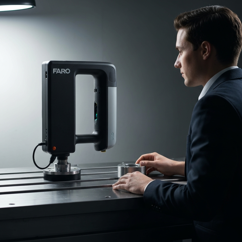
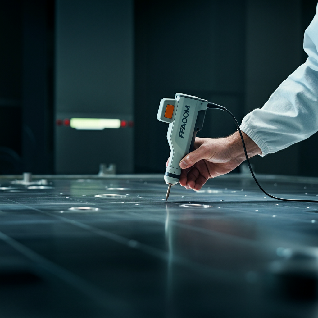
Begin by placing both the FARO ScanArm and the object to be measured on stable, vibration-free surfaces. Ensure the ScanArm's mounting base is securely attached to its support, often a magnetic base or a dedicated stand. This is critical for accurate measurements. Position the ScanArm such that it can reach all areas of the workpiece you need to inspect without straining the arm's joints. Double-check the reach BEFORE rigidly mounting to avoid repositioning later.
Connecting the Arm
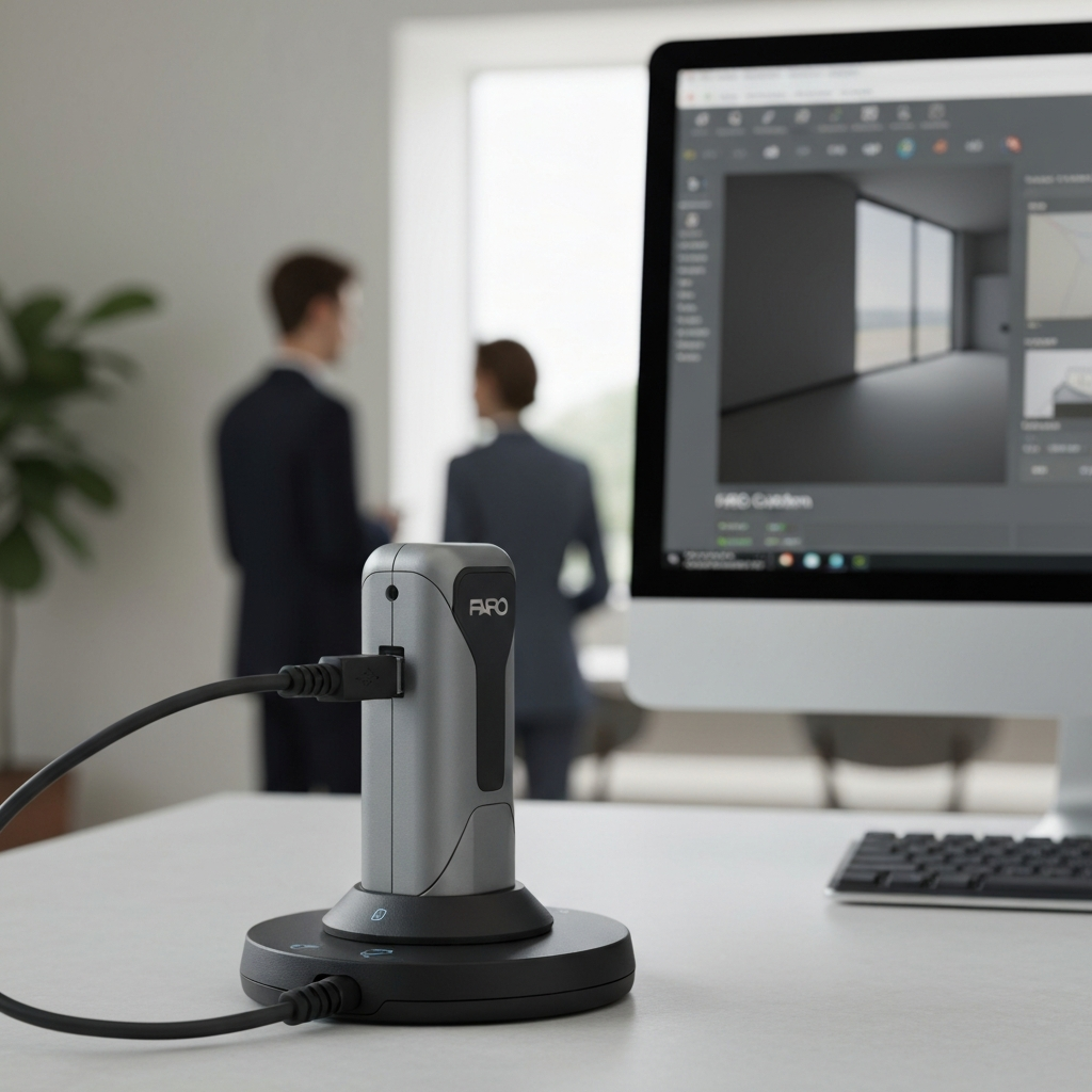
Connect the FARO ScanArm to your computer using the provided USB 3.0 cable. Ensure the cable is securely plugged into both the ScanArm and the computer. Launch the FARO CAM2 2019 software. Once the software is running, power on the ScanArm. CAM2 should automatically detect the connected ScanArm. If it doesn't, check the USB connection and ensure the necessary drivers are installed. Driver installation is typically automated but can sometimes require manual intervention from the device manager.
Verifying Arm Functionality
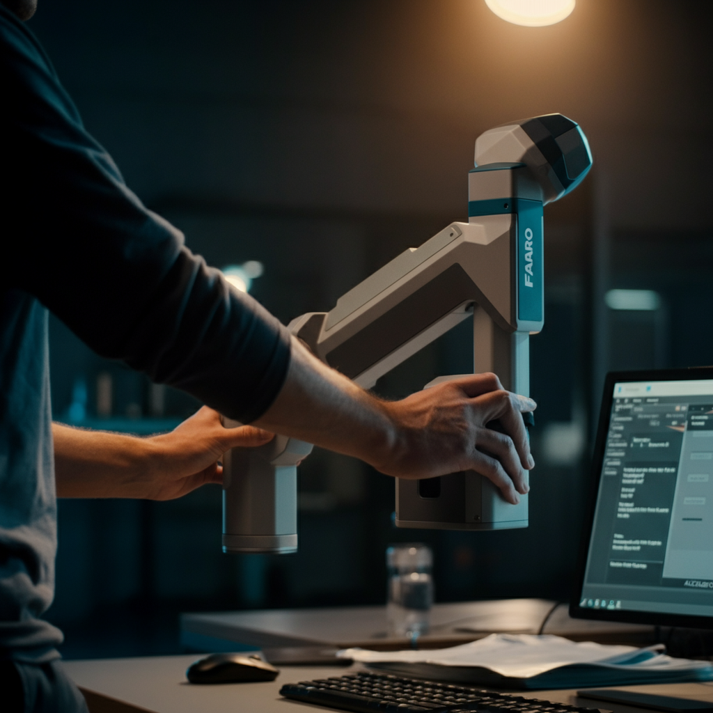
Once connected, visually inspect all joints of the ScanArm for smooth movement and proper operation. CAM2 2019 typically displays a graphical representation of the ScanArm with color-coded joint indicators. These indicators usually turn green when the joint is moving freely within its operational limits. Red indicators signal potential issues, such as joint limits being reached or hardware problems. Test all joints by carefully rotating them through their full range of motion. Address any issues with joint movement before proceeding; excessive force can damage the arm.
Step 2: Loading the CAD Model
Importing the CAD File
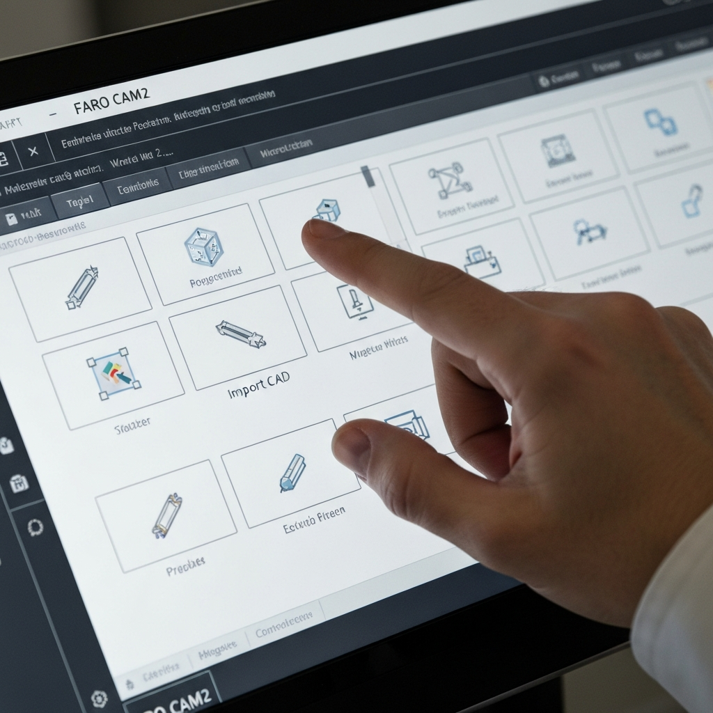
To compare the physical part to its intended design, you need to load the corresponding CAD model into CAM2 2019. Navigate to the "Home" tab in the CAM2 interface and select the "Import CAD" icon. CAM2 supports a variety of CAD file formats, including STEP, IGES, and native formats like SolidWorks and CATIA. Select the appropriate file from your computer's file system and click "Open."
Positioning and Orienting the Model
After importing the CAD model, it may appear in a different position or orientation than the physical part. Use the CAM2's transformation tools (translate and rotate) to roughly align the CAD model with the physical part within the software's virtual space. This initial alignment doesn't need to be perfect; it just needs to be close enough to facilitate the creation of a precise alignment system in the next step. Failing to perform this rough alignment will lead to confusion later.
Step 3: Creating an Alignment System
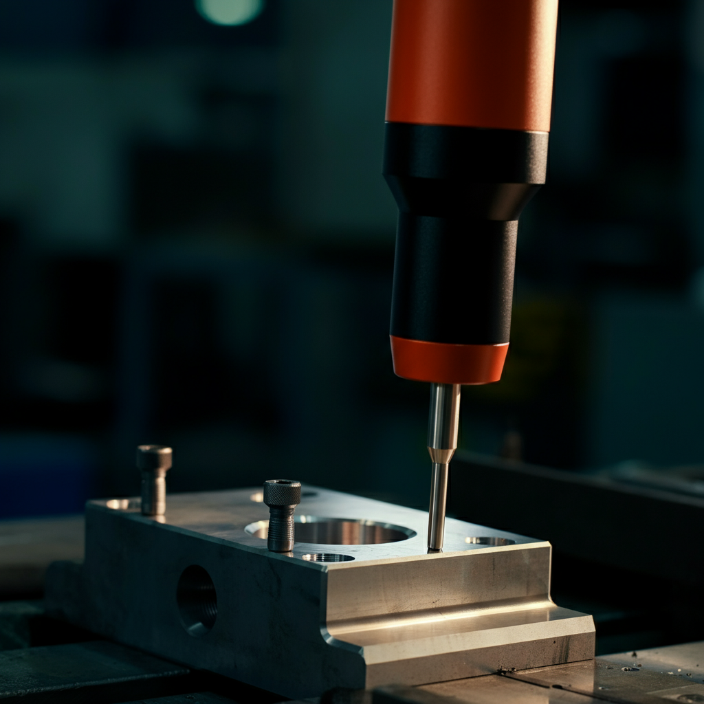
Measuring the Primary Plane
A crucial step in accurate measurement is establishing a coordinate system that aligns the physical part with the CAD model. Start by selecting the "Plane" icon from the "Measure" tab. Touch the probe to the physical part on a flat surface that corresponds to a plane in the CAD model. Press and release the green button on the ScanArm handle. Repeat this process at least three more times, ensuring each point is on the same plane and spread out to define the plane accurately. Finally, press and release the red button to complete the plane measurement. The more points used to define the plane, the more accurate the alignment will be. Aim for consistent pressure and probe placement.
Measuring the 2D Line
Next, select the "2D Line" icon on the "Measure" tab. Choose a line feature on the part that corresponds to a line in the CAD model, located on the previously measured plane. Touch the probe to the part on the line and press and release the green button. Move the probe to another point along the same line and press and release the green button again. Press and release the red button to complete the line measurement. Ensure the two points are far enough apart to accurately define the line's direction. Avoid measuring very short lines, as small errors can have a significant impact.
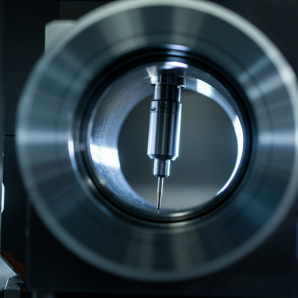
Measuring the Circle
Now, select the "Circle" icon on the "Measure" tab. Identify a circular feature on the part (typically a hole) that lies on the previously measured plane. Place the probe inside the circle and touch the inner edge. Press and release the green button. Repeat this process at least four times, distributing the points around the circumference of the circle. Cover at least 1/3 of the circumference for best results. Press and release the red button to complete the circle measurement. Ensure the probe is perpendicular to the plane of the circle for each measurement. Any wobble will lead to an inaccurate circle measurement.
Defining the Coordinate System
Select the "Coordinate System" icon located on the "Alignments" tab. Use the Coordinate System Wizard, which simplifies the process by guiding you through the selection of the plane, line, and circle features you just measured. Assign the appropriate axes and vectors to each feature to match the coordinate system of the CAD model. Carefully review the axis orientations to ensure they align correctly. Incorrect axis assignments will result in a mirrored or rotated alignment. If necessary, use the "Offset" option to specify the circle's location as the origin of the coordinate system. Click the green "OK" button, then the red "Cancel" button to exit the wizard.
Verifying and Refining the Alignment
After creating the coordinate system, visually verify that the measured part and the CAD model are properly aligned within the CAM2 interface. You can use the "Inspect Surface Point" tool on the "Measure" tab to measure points on the part and compare their coordinates to the CAD model. If the alignment is not satisfactory, double-click the coordinate system in the "Features" pane to edit its parameters. Adjust the vectors, offsets, or feature selections as needed and repeat the verification process. Iterate until you achieve a satisfactory alignment. A precise alignment is critical for accurate measurements.
Step 4: Measuring the Assembly
Measuring Surface Points
To inspect the surface of the assembly, select the "Inspect Surface Point" icon on the "Measure" tab. Touch the probe to the surface of the assembly at the desired location and press and release the green button. The Feature Measurement window will display the Cartesian coordinates of the measured point and the Distance to Nominal (Dn), which represents the deviation between the measured point and the corresponding point on the CAD model. This method is ideal for spot checks or measuring specific locations on the surface.
Continuous Surface Scanning
For more comprehensive surface inspection, you can use the continuous scanning mode. Select the "Mode" dropdown menu in the Feature Measurement window and choose the "Distance" option. Enter a desired distance increment (e.g., 4.0 inches). Now, touch the probe to the surface, press and release the green button, and slide the probe along the surface. CAM2 will automatically collect measurement data every 4 inches as you move the probe. Press and release the red button to pause the measurement, and press it twice to stop the measurement operation. Maintain consistent contact with the surface and a steady movement speed for optimal results.
Measuring Circles and Holes
To measure circles or holes, select the "Circle" icon on the "Measure" tab. Click the dropdown arrow in the Projection Plane group and select "Define." Measure at least four points around the hole, defining a plane. Press and release the red button when finished defining the plane. Then, place the probe inside the hole and touch the wall of the hole. Press and release the green button. Move the probe slightly and take another point touching the wall of the hole. Measure at least four locations covering at least 30% of the circumference. Press and release the red button when finished. Repeat this process for all holes that require measurement. Remember to keep consistent contact, and distribute the measurement points as evenly as possible around the circumference.
Measuring Round Slots
To measure round slots, select the "Round Slot" icon in the "Measure" tab. Click the dropdown arrow in the Projection Plane group and select “Define”. Measure at least four locations around the slot to define a plane. Press and Release the green button for each point on the plane. P&R the Red button when finished. Place probe into and touch the wall of the slot. Press and Release the Green Button, move the probe and measure another location touching the wall of the slot. Measure at least 2 locations on both sides of the slot and both ends, 8 measurements total. Press and Release the Red Button when finished. Repeat this step for all slots that require measurement. It is important to measure points on both ends of the slot to fully define its length and position.
Measuring Spheres
Select "Sphere" on the measure tab. Place the probe in contact with the sphere, Press and Release the Green Button. Moving the probe around the surface of the sphere Press and Release the Green button at least 6 more times. Move the probe above the sphere, Press and Release the RED button when completed. Try to distribute the points evenly across the surface of the sphere to get a more accurate measurement.
Step 5: Picking Nominal Features from CAD
Selecting Features from CAD
To associate measured features with their corresponding nominal features in the CAD model, select the "Pick From CAD" tab on the main toolbar. The system may automatically suggest the feature being picked based on proximity, or you can manually select the feature type from the dropdown menu. For complex parts, manual selection is generally more reliable. For example, if you measured a circle, select "Other Features" and click on the "CIRCLE" option.
Associating Measured and Nominal Features
After selecting the feature type, manipulate the CAD model to zoom in on the corresponding feature you measured. Left-click on the CAD feature to select it. Repeat this process for all measured features that you want to associate with nominal data. Click "Cancel" on the "Pick" window when finished. Ensure you are selecting the correct feature on the CAD model; misidentification will lead to inaccurate reporting.
Combining Nominal and Measured Data
In the "Features" pane of the user interface, select the nominal data point (picked from the CAD model) by left-clicking on its name. Then, left-click and hold the name and drag it on top of the corresponding measured feature in the list. Releasing the mouse button will combine these two items, linking the measured data to the nominal data from the CAD model. Repeat this process for all nominal features as needed. This association is crucial for generating meaningful reports that compare measured values to design specifications.
Step 6: Reporting
Creating a Report
Once you have completed the measurements and associated them with the CAD model, you can generate a report to summarize the results. Click on the "Report" icon at the bottom of the "Features" pane of the user interface. The icon resembles a piece of paper. This will open the report generation window. CAM2 offers a variety of report templates and customization options to tailor the report to your specific needs.
Adding a Document Header
Click on the "Document Header" icon on the "Home" tab of the report window. A pop-up window will open, providing labeled fields for you to complete. Enter the required information, such as the report title, author, date, and any other relevant details. Click the "OK" button to save the header information. A well-defined document header adds professionalism and context to your report.
Including Features in the Report
Click the "Include Feature" icon. A pop-up window will open, displaying all the measured features on the left and an empty pane on the right. Select the features you want to include in the report by individually selecting them and pressing the single right-facing arrow. This will move the selected features to the right pane, indicating that they will be included in the report. Carefully select the features relevant to your analysis to avoid cluttering the report with unnecessary data.
Printing the Report
Finally, click the "Printer" icon to print the report. A pop-up window will open, providing access to the local printer options. Select your desired printer and configure the printing settings as needed. Follow the prompts to print the report. Before printing, preview the report to ensure it contains the information you need and is formatted correctly.
Tools or Materials Required
- FARO ScanArm
- FARO CAM2 2019 Software
- Computer with USB 3.0 port
- Calibration artifacts (sphere, plane)
- Stable mounting base for the ScanArm
- CAD model of the part being measured
Common Mistakes to Avoid
- Inadequate Probe Calibration: Always calibrate the probe before starting measurements.
- Unstable Setup: Ensure the ScanArm and workpiece are on stable surfaces.
- Incorrect Alignment: Double-check the alignment before taking critical measurements.
- Exceeding Arm's Reach: Position the arm so it can reach all measurement points without straining the joints.
- Ignoring Environmental Factors: Temperature changes can affect measurement accuracy; allow parts to acclimate to the environment.
Safety Considerations
- Always wear appropriate personal protective equipment (PPE), such as safety glasses.
- Be aware of the ScanArm's range of motion and avoid collisions with surrounding objects.
- Keep the work area clean and free of clutter to prevent tripping hazards.
- Follow the manufacturer's instructions for safe operation and maintenance of the ScanArm.
FAQ Section
- Q: How often should I calibrate the probe?
- A: Calibrate the probe whenever you change probe tips, move the ScanArm to a new location, or suspect a loss of accuracy.
- Q: What file formats does CAM2 2019 support for importing CAD models?
- A: CAM2 2019 supports a wide range of CAD file formats, including STEP, IGES, DXF, and native formats like SolidWorks and CATIA.
- Q: Can I use a wireless connection with the ScanArm?
- A: Yes, newer ScanArms support wireless connections (Wireless LAN and Bluetooth). Ensure your ScanArm and computer are properly configured for wireless communication.
Conclusion
Using a FARO ScanArm with CAM2 2019 is a powerful method for precise 3D measurement and inspection. By following the steps outlined in this guide, you can effectively set up the equipment, create accurate alignments, measure parts, and generate comprehensive reports. Remember that careful attention to detail, proper calibration, and a stable setup are essential for achieving reliable and accurate results. With practice and experience, you'll be able to leverage the full potential of this technology for a wide range of applications.