Geometric Dimensioning and Tolerancing (GD&T) is a precise language used in engineering drawings to define the allowable variation in the geometry of parts. It uses a standardized set of symbols and rules to communicate manufacturing requirements clearly, reducing ambiguity and ensuring parts meet specific design intentions. Mastery of GD&T symbols is essential for designers, machinists, and inspectors involved in manufacturing processes.
This guide provides an in-depth look at the most common GD&T symbols, categorized by the type of tolerance they define. We’ll explain what each symbol represents, its typical application, and how it’s used within a Feature Control Frame (FCF). Learning GD&T can initially seem daunting, but understanding these symbols enables clear and effective communication throughout the manufacturing lifecycle, leading to higher quality products and reduced production costs.
By the end of this guide, you will have a solid understanding of the primary GD&T symbols, their meaning, and how to interpret them within engineering drawings. We’ll also touch on the importance of understanding the standards that govern GD&T practices globally.
Step 1: Understanding Feature Control Frames (FCF)
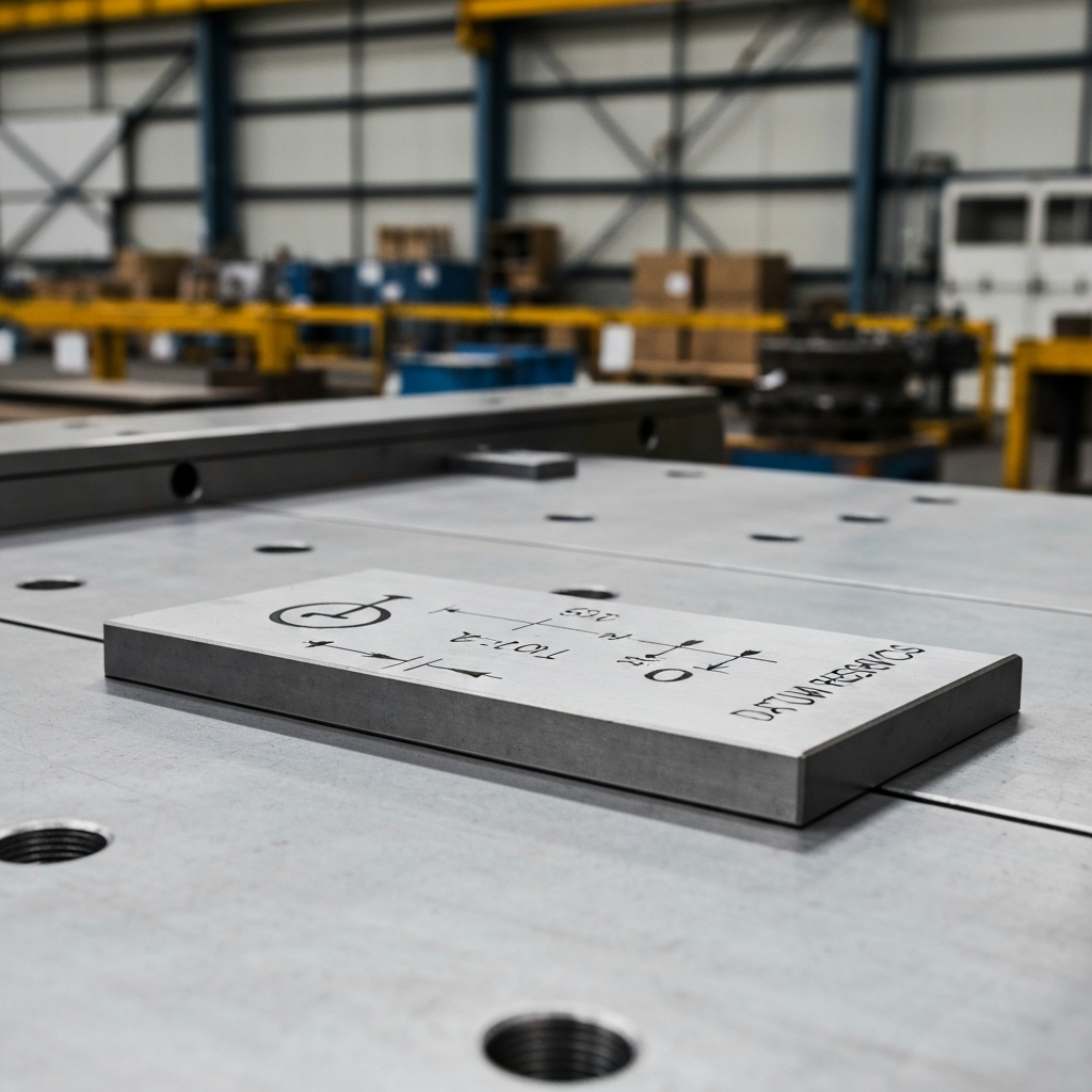
A Feature Control Frame (FCF) is the rectangular box that contains the GD&T instructions on a technical drawing. It acts as the "sentence" that communicates the tolerance requirements for a specific feature. Understanding how to read an FCF is fundamental to interpreting GD&T symbols effectively. The frame is read from left to right, and each section contains critical information about the tolerance.
An FCF always begins with the GD&T symbol itself, indicating the type of tolerance being specified (e.g., flatness, position, etc.). Following the symbol, you'll find the tolerance value, which defines the permissible variation for the feature. Modifiers, such as Maximum Material Condition (MMC) or Least Material Condition (LMC), may also be present, adding further context to the tolerance requirements. Finally, the FCF may include datum feature references, which specify the reference points from which measurements should be taken. Ignoring any part of the FCF can lead to misinterpretation and potentially, incorrectly manufactured parts.
Step 2: Form Tolerance Symbols
Form tolerances control the shape of individual features, irrespective of their relationship to other features. They define acceptable deviations from the "perfect" form of a feature. Four main form tolerances are commonly used in GD&T: Straightness, Flatness, Circularity, and Cylindricity.
2.1 Straightness (▬)
Straightness controls how much the straightness of a feature can vary along its axis or center compared to its “perfect form” (or theoretical ideal). The tolerance zone is defined by two parallel lines a set distance apart. It is commonly used for features such as shafts and pins. The Unicode for this symbol is 25AC. When specifying straightness, be mindful of the feature's length; a tight tolerance on a long feature may be difficult and costly to achieve.
2.2 Flatness (▱)
Flatness specifies how much deviation is allowed between the highest and lowest points on a surface. The tolerance zone for flatness is also defined by two parallel lines a pre-determined distance apart. It's often used on joining surfaces to ensure proper contact. The Unicode for this symbol is 25B1. When applying flatness, ensure the measuring equipment can accurately detect deviations within the specified tolerance.
2.3 Circularity (◯)
Circularity, also known as roundness, specifies how much a cross-section of a round object can deviate from a true circle. The tolerance zone is defined by the space between two concentric circles. It’s commonly applied to bores and bearings. The Unicode for this symbol is 25EF. A common mistake is applying circularity when cylindricity is more appropriate.
2.4 Cylindricity (⌭)
Cylindricity defines how much a feature can deviate from a true cylinder shape. It considers both the axis and the round surface, making it more comprehensive than circularity. The tolerance zone is defined by two concentric cylinders. It is frequently used for precision guides and sleeves. The Unicode for this symbol is 232D. Achieving cylindricity can be challenging, requiring specialized machining techniques and measuring equipment.
Step 3: Profile Tolerance Symbols
Profile tolerances control the shape and size of a feature's surface. There are two main profile tolerances: Profile of a Line and Profile of a Surface. These tolerances define a boundary within which the feature's surface must fall.
3.1 Profile of a Line (⌒)
The profile of a line (also called the line profile) of a feature is a two-dimensional tolerance zone. It determines the feature’s profile if you were to take a cross-section at a specific point. It is commonly used for features like cams and blades. The Unicode for this symbol is 2312.
3.2 Profile of a Surface (⌓)
The profile of a surface (or surface profile) of a feature is a 3D tolerance zone. It demonstrates where the surface of a feature should be – so in essence, it controls the size and shape of the form. This tolerance can be applied to either flat or curved surfaces. It's commonly used for castings. The Unicode for this symbol is 2313.
Step 4: Orientation Tolerance Symbols
Orientation tolerances control the angle or relationship between features. They define how features should be oriented with respect to each other or to a datum. The primary orientation tolerances are Angularity, Perpendicularity, and Parallelism.
4.1 Angularity (∠)
Angularity refers to the angle of a surface in relation to the datum feature. This is used when a feature needs to sit at an angle other than 90°. The tolerance zone for angularity is defined by two parallel planes that intersect the datum feature at the required angle. Common applications include slopes and tapers. The Unicode for this symbol is 2220.
4.2 Perpendicularity (⟂)
Perpendicularity of a feature describes the tolerance of variation allowed between a surface that is meant to sit at a 90° angle to the datum feature or another surface. The tolerance zone is defined by two parallel planes that run perpendicular to the datum feature. It is frequently used for mounting faces. The Unicode for this symbol is 27C2. When specifying perpendicularity, ensure the datum is clearly defined and easily accessible for measurement.
4.3 Parallelism (∥)
Parallelism of a feature is similar to straightness, but it determines how much a parallel surface can deviate from a datum feature or another parallel plane. The tolerance zone is determined by two planes that are parallel to the datum feature. Common applications include bearing rails. The Unicode for this symbol is 2225.
Step 5: Location Tolerance Symbols
Location tolerances control the position of features with respect to each other or to a datum. They define where a feature should be located within a part. The main location tolerances are True Position, Concentricity, and Symmetry.
5.1 True Position (⌖)
The true position (or simply position) tolerance defines how much the location of a feature can vary relative to the rest of the form. In other words, it specifies exactly where a feature (like a hole) must be located. The tolerance zone is typically a circle or cylinder around the feature. Applications include assemblies and bolt holes. The Unicode for this symbol is 2316.
5.2 Concentricity (◎)
Concentricity defines the variation in two cylinders that are meant to have the same central axis. It’s used to ensure two round features (like a bolt and a hole) are aligned. The central axis is used as the datum feature. Common applications include gears and rotating parts. The Unicode for this symbol is 25CE.
5.3 Symmetry (⌯)
The symmetrical tolerance of a feature refers to the variance allowed in two planes in relation to a central datum feature. This is useful when two parts need to be a mirror image of each other. It’s often used for supports and brackets. The Unicode for this symbol is 232F.
Step 6: Runout Tolerance Symbols
Runout tolerances control the variation of a surface or feature as it rotates around an axis. There are two main runout tolerances: Total Runout and Circular Runout.
6.1 Total Runout (⌰)
The total runout (sometimes just called runout) of a feature determines how much the surface of a rotating part can vary around the central axis. The tolerance zone is made up of two concentric cylinders. Applications include crankshafts and rotors. The Unicode for this symbol is 2330.
6.2 Circular Runout (↗)
The circular runout is similar to the total runout, but two-dimensional. It determines how much the circumference of a cylindrical part can vary at any point along its length, based on the distance from the surface to the central axis when viewed as a cross-section. Circular runout focuses on individual circular elements, while total runout considers the entire surface. The Unicode for this symbol is 2197.
Common Mistakes to Avoid
- Misinterpreting Datum References: Incorrectly identifying or applying datum references can lead to significant errors in measurement and manufacturing. Always double-check the datum scheme and ensure it is clearly understood.
- Using the Wrong Symbol: Selecting the wrong GD&T symbol can result in incorrect tolerances being applied. For instance, using circularity when cylindricity is more appropriate for a cylindrical feature.
- Ignoring Modifiers: Modifiers like MMC or LMC significantly impact the tolerance zone. Failing to account for them can lead to parts that don't fit or function as intended.
- Over-Tolerance: Specifying tolerances that are tighter than necessary can increase manufacturing costs significantly without adding value.
- Under-Tolerance: Specifying tolerances that are too loose can result in parts that do not function or fit properly, leading to product failure.
Pro Tips
- Start with Simple Tolerances: Begin by understanding basic tolerances like flatness and straightness before moving on to more complex concepts like profile and runout.
- Practice Reading Drawings: Regularly practice reading engineering drawings with GD&T to improve your interpretation skills.
- Use GD&T Software: Utilize GD&T software to simulate tolerance stack-ups and visualize the impact of different tolerances on part functionality.
- Stay Updated with Standards: The governing standards for GD&T, such as ASME Y14.5 and ISO 1101, are periodically updated. Stay informed about the latest revisions.
- Attend Training Courses: Consider attending formal GD&T training courses to gain a deeper understanding of the subject.
FAQ Section
- What are the governing standards for GD&T?
- The current governing standards for GD&T are ASME Y14.5-2018 (US), ISO 1101 (International), and BS 8888 (UK).
- Why is GD&T important?
- GD&T allows for precision when manufacturing complex parts. It gives the designers and manufacturers a language they can use to precisely communicate the specifications of a part and all its features. It also defines allowable variances, making it easy to determine whether or not a part meets specifications. This ensures that a part will fit perfectly with other parts in a finished product.
- Where is GD&T used?
- GD&T is often used in the automotive, aerospace, and medical device industries.
Conclusion
Understanding GD&T symbols is paramount for effective communication and precision in manufacturing. By mastering the concepts outlined in this guide, including the meaning of each symbol, how to interpret Feature Control Frames, and common mistakes to avoid, you can significantly improve the quality and efficiency of your manufacturing processes. Remember to stay updated with the latest GD&T standards and seek out opportunities for continued learning and practice.